0%

【漫漫科研路\pgfplots】画局部放大图

在科研论文写作中,我们经常需要放大局部图片来显示细节,即绘制图中图。在Matlab中可以使用magnify或则axes函数,网上有很多例子,这里不再赘述。本文主要讲解如何使用tikz/pgfplots来画局部放大图中图。

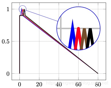
绘制局部放大图,需要使用到spy宏包,本文主要参考pgfplots手册。下面给出一个最简单的实例,具体代码如下:

1
2
3
4
5
6
7
8
9
10
11
12
13
14
15
16
17
18
19
20
21
22
23
24
25
26
27
28
29
30
\documentclass[10pt, final, journal, twocolumn, oneside]{IEEEtran}

%!TEX program = xelatex
% !TEX encoding = UTF-8 (utf8)
%!TEX spellcheck
\def\pgfsysdriver{pgfsys-dvipdfmx.def}
\usepackage{tikz}

\usepackage{pgfplots}
\usetikzlibrary{spy} %
\pgfplotsset{width=7cm,compat=1.14}


\begin{document}

\begin{tikzpicture}[spy using outlines= {circle, magnification=6, connect spies}]
% define the shape of spy: circle or rectangle
\begin{axis}[no markers,grid=major, every axis plot post/.append style={thick}]
\addplot coordinates {(0, 0) (0, 0.9) (1, 0.9) (2, 1) (3, 0.9) (80, 0)};
\addplot+ [line join=round] coordinates {(0, 0) (0, 0.9) (2, 0.9) (3, 1) (4, 0.9) (80, 0)};
\addplot+ [line join=bevel] coordinates {(0, 0) (0, 0.9) (3, 0.9) (4, 1) (5, 0.9) (80, 0)};
\addplot+ [miter limit=5] coordinates {(0, 0) (0, 0.9) (4, 0.9) (5, 1) (6, 0.9) (80, 0)};

\coordinate (spypoint) at (3,1);% The point to be magnified
\coordinate (magnifyglass) at (60,0.7);% The point where to see
\end{axis}

\spy [blue, size=2.5cm] on (spypoint) in node[fill=white] at (magnifyglass);
\end{tikzpicture}
\end{document}

结果如下:
图1


代码简单易懂,也给出了部分注释。为了使得更加个性化,我们可以修改放大图的轮廓,或则背景色,具体代码如下:

1
2
3
4
5
6
7
8
9
10
11
12
13
14
15
16
17
18
19
20
21
22
23
24
25
26
27
28
29
\documentclass[10pt, final, journal, twocolumn, oneside]{IEEEtran}

%!TEX program = xelatex
% !TEX encoding = UTF-8 (utf8)
%!TEX spellcheck
\def\pgfsysdriver{pgfsys-dvipdfmx.def}
\usepackage{tikz}

\usepackage{pgfplots}
\usetikzlibrary{spy} %
\pgfplotsset{width=7cm,compat=1.14}


\begin{document}
\begin{tikzpicture}[spy using overlays= {rectangle, magnification=6, connect spies}]
% define the shape of spy: circle or rectangle
\begin{axis}[no markers,grid=major, every axis plot post/.append style={thick}]
\addplot coordinates {(0, 0) (0, 0.9) (1, 0.9) (2, 1) (3, 0.9) (80, 0)};
\addplot+ [line join=round] coordinates {(0, 0) (0, 0.9) (2, 0.9) (3, 1) (4, 0.9) (80, 0)};
\addplot+ [line join=bevel] coordinates {(0, 0) (0, 0.9) (3, 0.9) (4, 1) (5, 0.9) (80, 0)};
\addplot+ [miter limit=5] coordinates {(0, 0) (0, 0.9) (4, 0.9) (5, 1) (6, 0.9) (80, 0)};

\coordinate (spypoint) at (3,1);% The point to be magnified
\coordinate (magnifyglass) at (60,0.7);% The point where to see
\end{axis}

\spy [green,size=2.5cm] on (spypoint) in node at (magnifyglass);
\end{tikzpicture}
\end{document}

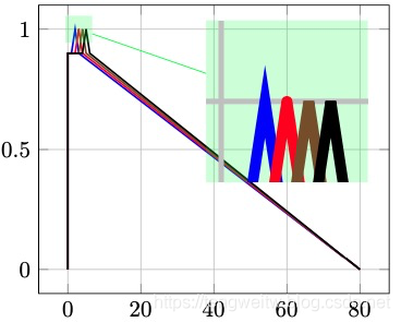
显示效果如下:
图2


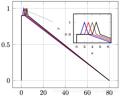
由上图可以看到,相比于Matlab,这里局部放大图更加灵活和个性化。但是Matlab的局部放大图一般都有坐标轴,方便查看局部图的值大小。在Tikz/pgfplots中利用Spy宏包实现相同的效果比较困难。但是我们可以另辟蹊径: 只需要利用node,在node中重新画一个图,只是自己设置横纵坐标的值,从而实现局部放大。具体代码实现如下:

1
2
3
4
5
6
7
8
9
10
11
12
13
14
15
16
17
18
19
20
21
22
23
24
25
26
27
28
29
30
31
32
33
34
35
36
37
38
39
40
41
42
\documentclass[10pt, final, journal, twocolumn, oneside]{IEEEtran}

%!TEX program = xelatex
% !TEX encoding = UTF-8 (utf8)
%!TEX spellcheck
\def\pgfsysdriver{pgfsys-dvipdfmx.def}
\usepackage{tikz}

\usepackage{pgfplots}
\usetikzlibrary{spy} %
\pgfplotsset{width=7cm,compat=1.14}


\begin{document}
\begin{tikzpicture}[pin distance=1.5cm]
\begin{axis}[no markers,grid=major, every axis plot post/.append style={thick}]
\addplot coordinates {(0, 0) (0, 0.9) (1, 0.9) (2, 1) (3, 0.9) (80, 0)};
\addplot+ [line join=round] coordinates {(0, 0) (0, 0.9) (2, 0.9) (3, 1) (4, 0.9) (80, 0)};
\addplot+ [line join=bevel] coordinates {(0, 0) (0, 0.9) (3, 0.9) (4, 1) (5, 0.9) (80, 0)};
\addplot+ [miter limit=5] coordinates {(0, 0) (0, 0.9) (4, 0.9) (5, 1) (6, 0.9) (80, 0)};
\coordinate (spy_point) at (axis cs:0,1);
\end{axis}
%plot the magnified figure using a node
\node[pin=-5:{%
\begin{tikzpicture}
\begin{axis}[no markers, thick,scale=0.8,
tiny,
xlabel={x},
ylabel={y},
xmin=0,xmax=8,
ymin=0.85,ymax=1.05,
enlargelimits,
]
\addplot coordinates {(0, 0) (0, 0.9) (1, 0.9) (2, 1) (3, 0.9) (80, 0)};
\addplot+ [line join=round] coordinates {(0, 0) (0, 0.9) (2, 0.9) (3, 1) (4, 0.9) (80, 0)};
\addplot+ [line join=bevel] coordinates {(0, 0) (0, 0.9) (3, 0.9) (4, 1) (5, 0.9) (80, 0)};
\addplot+ [miter limit=5] coordinates {(0, 0) (0, 0.9) (4, 0.9) (5, 1) (6, 0.9) (80, 0)};

\end{axis}
\end{tikzpicture}%
}] at (spy_point) {};
\end{tikzpicture}

结果如下:
图3

坚持原创技术分享,您的支持将鼓励我继续创作!